Revolutionary power grid monitoring and analysis
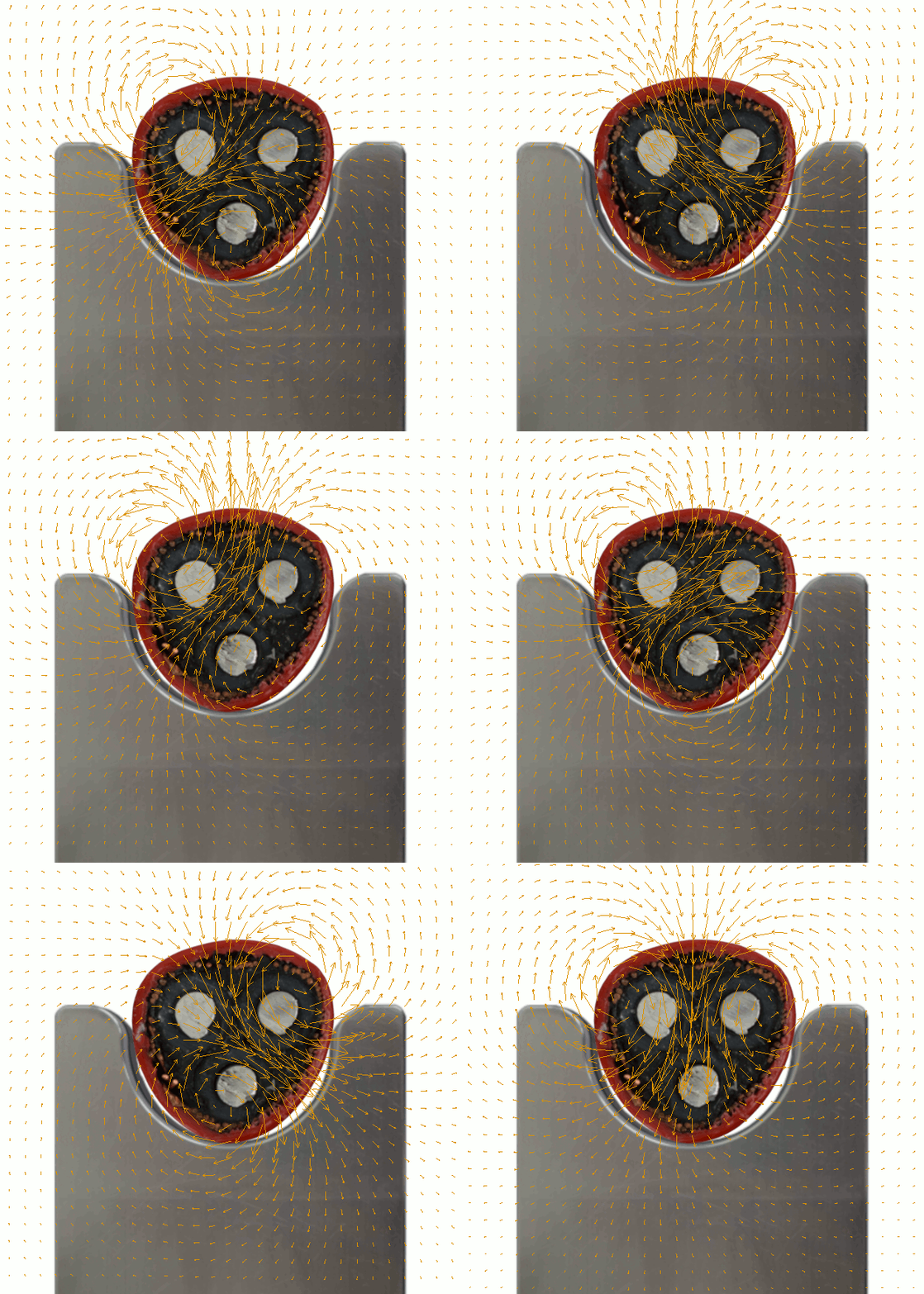
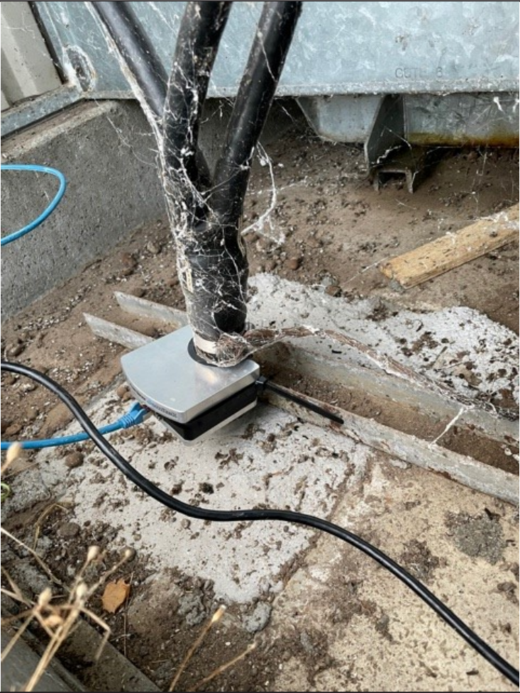
An I3 Power Sensor mounted on a 3-phase medium voltage cable, which illustrates the magnetic field generated by a three phase current.
The I3 Power Sensor system measures voltage, current and derived quantities, i.e. reactive power, THD, earth faults, for multiple conductors in power grid installations.
A breakthrough in multi phase current measurement
A unique and patented feature of the I3 sensor system is the ability to measure currents of individual conductors directly on a 3 phase screened cable, with no need for calibration.
Follow this link for a live demonstration of
The graphical web interface of the I3 Power Sensor
Operates as a localized mini SCADA
The sensor features an integrated computing platform, allowing for high speed and high level data processing, full lifetime data logging, frequency (FFT) analysis, alarm reporting, and support for multiple Ethernet based communication protocols.
High quality raw measurement data as a foundation ..
Voltage and current measurements, joint specification
- Frequency content up to the 312th harmonic @ 50Hz (31250Hz sample rate)
- Excellent linear pass band performance,
- Power line communication artifacts eliminated via >79dB signal suppression from 16kHz and up
Voltage measurements
- Up to 4x voltage inputs
- Typical 1 second RMS resolution and range of 10mV up to 20kV @ 10kV nominal rating
- No voltage measurement transformer – input signal via compact high voltage capacitor
- Nominal voltage rating from 100V to 50kV+
- Absolute measurement accuracy from 0.5% of nominal level, depending on type of HV capacitor
- Relative measurement accuracy 0.1%, with excellent wide band performance (industry standard measurement transformers are often not specified outside of 50/60Hz usage, making transient waveform analysis misleading in most cases)
Current measurements
- Automatic tracking of up to 5 currents (physical conductors)
- Typical 1 second RMS resolution and range of 1mA up to 8kA
- No current measurement transformer – input signal via integrated magnetic field sensors
- Absolute measurement accuracy from 1%+-100mA, depending on cable geometry. Typically ~2-3% for a 3 phase cable.
.. enabling localized processing and analysis ..
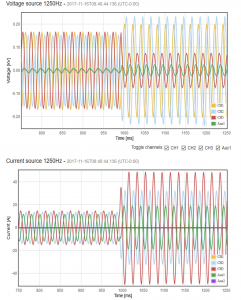
I3 Power Sensor example event waveform made available via the integrated web server, with fully synchronous recording of all voltage and current channels
Automatic event detection, logging and analysis
- High level parameter readout including configurable time span true RMS of
- Voltage
- Current
- Apparent power
- Reactive power
- Real (active) power
- Phase difference between voltage and current
- Power factor
- Total Harmonic Distortion, THD, readout according to EN50160, and additional configurable THD variants
- Automatic logging of current and voltage waveforms
- Event triggered logging of waveforms, e.g. transition from normal operation to short circuit or earth fault state
- Directional detection of short circuits and earth faults

.. leading to high value Smart Grid operational information
Load monitoring
- Enables targeted upgrades of stressed sections of the power grid, and improved load distribution during normal operation
- Provides an overview of non-linear loads via frequency analysis on the electrical current
Fault reporting
- Directional detection of short circuits, enabling shortened downtime via quick reestablishment of power to the surrounding grid.
- Directional detection of both high and low impedance earth faults, which can severely affect the lifetime of the power grid infrastructure, and may go unnoticed for years at a time, or be extremely difficult to identify, in terms of the area at fault
Lifetime assessment
- Reveal transformer operational health state prior to breakdown via frequency analysis (FFT and THD data) combined with long term load profile data, to enable timely replacement of equipment, and prolong the lifetime where possible
The Jomitek I3 Power Sensor
- Designed to last >20 years in outdoor environments
- Highly optimized for low bandwidth requirements, conforming with IoT cellular service capabilities
- Extremely easy installation, and no calibration requirements
- Features unique capabilities in current measurement and earth fault detection reporting
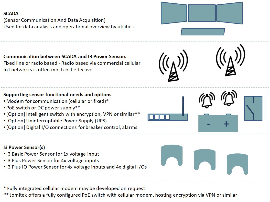
I3 Power Sensor system overview
Further product details can be found in the I3 Power Sensor User Manual. Please contact Jomitek if there are further questions or request for quotes for particular solutions.

